This page has been translated with google translate, there may be errors in the stories.
Dynastart
The dynastart is a dynamo and starter motor in one and was mainly used in the 50s, 60s and early 70s on small diesel diesels with little power. Because the dynastart does not give much power as a starter motor, it was only applied to small diesels and in addition, the loading capacity of the dynastart is also limited, the loading capacity and amount to 11 amps. The dynastart works with direct current, but because the direct current alternators were not very efficient and with the advent of the alternator which is smaller and gave much more payload, the dynastart disappeared.
Operation of the dynastart.
A dynastart is equipped with an external controller with 3 relays that ensure that the dynastart can start an engine and charge a battery. Of the 3 relays, two have a common core, the start relay is a separate relay that is separate from the charging system. The first rail is a start relay that connects as soon as the ignition lock is turned or the push button is pressed to start. The positive of the battery with contact 30 on the dynastart is then connected. The second relay connects the battery to the dynastart as soon as it supplies enough voltage and ensures that as long as the charging voltage is lower than the battery voltage, no current can flow from the battery to the dynastart. The third relay controls the generated voltage. The controller therefore has three relays, 2 of which are used to control charging and the third relay is used to start and is separate from the other two which have a common core. The single relay contact of the control relay connects the battery to the dynastart, as soon as it supplies enough voltage. The changeover contact controls the field voltage and switches back and forth between ground and plus.
When the ignition is switched on, a current flows from the + pole of the battery through a lamp on the dashboard to the connection D + on the dynastart connected to ground via the rotor winding, the lamp lights up. By pressing the start button, connection 50 of the controller in start relay 1 is switched on. As a result, a current flows via connection 30H to connection 30 of the dynastart. The dynastart now works as a starter motor and starts the diesel engine. As soon as the engine is running and the start button is released, the dynastart is driven by the engine and starts charging. Where Df is connected to ground via changeover contact and Df in the dynastart is connected to D + via field windings, a current will flow from the D + via the field winding, D + changeover contact to ground. The field winding is now energized and the dynastart will now generate voltage and the charge lamp on the dashboard will go out.
The rising voltage at terminals D + of the dynastart causes a voltage difference between terminals Df and D + / 61 and an increasing current will flow through relay 3 of the controller. Relays 2 and 3 have a common core, so the increasing magnetic field in the core will cause relay 2 to be switched. Now connection D + is connected to the positive pole of the battery via connection D + / 61 of the controller and relay 2 and connection B + / 30, and as long as the supplied voltage is high enough, relay 2 will keep itself.
The different parts of a dynastart.
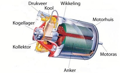
In the photo above you can see the different parts that you will find at a dynastart.
The anchor.
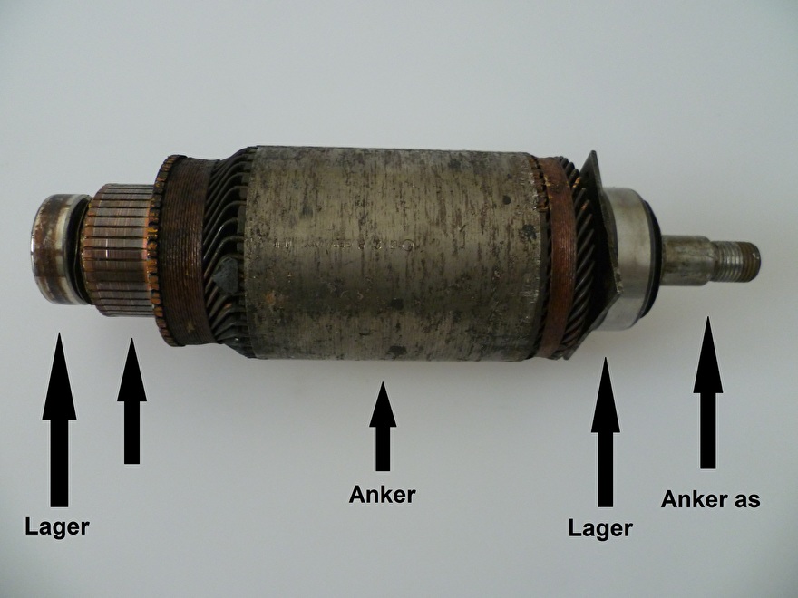
We call the rotating part of the dynastart the anchor. The bearings are pressed on the anchor and you will find the collector on which the carbon brushes make contact with the copper windings.
Carbon brushes.
The dynaster contains 4 carbon brushes, 2 positive carbon brushes and 2 negative carbon brushes. The carbon brushes are made of a relatively soft material so that they wear and do not damage the irreplaceable collector on the armature. The disadvantage is that due to the wear of the carbon brushes dirt builds up around the carbon brush bridge, this can cause a carbon brush to get stuck, so that no more contact is made with the collector. The carbon brushes can also lose contact with the collector because the carbon brushes have become too small due to wear. A spring pushes the carbon brushes down, but this stops if the carbon brush has become too small, the spring can no longer press the carbon brush onto the collector.
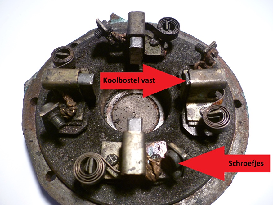
Carbon brush bridge.
Connections to the dynastart.
You will find 4 connections on the dynastart:
Terminal connection 30 is connected to the controller's 30h contact.
Clamp connection D- is connected to one of the mounting bolts of the controller
Terminal connection DF is connected to DF of the controller.
Terminal connection D + is connected to D + of the controller.
Often you will also find a minus cable from the battery connected to the dynastart, which is then attached to one of the mounting bolts, but it is also possible that the minus is somewhere else on the block.
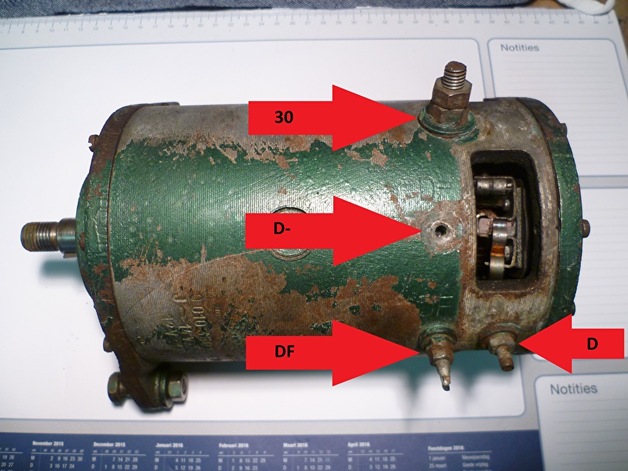
Connection diagram dynastart.
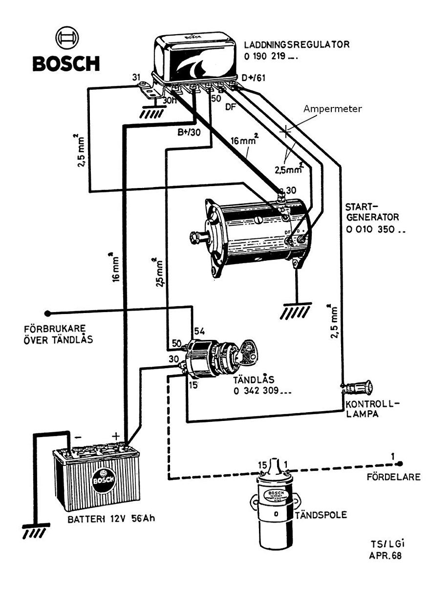
Controller.
The controller from Bosch is a mechanical controller with 3 rails, 1 for starting and 2 for charging the battery, the 2 used for charging have a common core. The controller is still being made but is then electronic, which is a plus especially for boats because the contacts can no longer oxidize.
Photo regulator old, and photo rusted regulator
The controller has the following connections.
Terminal connection 30H is connected to the 30 of the dynastart.
Clamp connection B + / 30 is connected to the positive pole of the battery.
Clamp connection 50 is connected to 50 of the ignition lock
Terminal connection DF is connected to the DF of the dynastart.
Terminal connection D + / 60 is connected to the control lamp on the dashboard and a wire goes from the light to the ignition switch on connection 15.
The following problems occur regularly with old dynastart:
Charge lamp broken
Corroded connections that prevent the dynastart from working properly.
Worn carbon brushes.
Short circuit in the wiring of the field winding, this can be due to carbon powder from the carbon brushes and / or extensive insulation material.
A defective charge controller. A defective charge controller causes the charging current to be too high.
V-belts slipping so that the dynastart does not work properly.
Maintenance of the dynastart.
The dynastart does not need annual maintenance, but there comes a time when the dynastart no longer wants to recharge or as a starter motor no longer works. It is not always easy to find out where the problem lies, but hope to give a helping hand with this piece to find the fault. First we check the wiring for a visible beech or if a connection has gone loose. A bad contact can also cause the dynastart to malfunction. It is advisable to loosen all contacts that you encounter on and around the dynastart and to clean them with fine sandpaper, and don't forget the charge controller, which is usually further away.
The average dynastart is already 40 years old and wear parts such as carbon brushes and bearings can eventually wear out, causing the dynastart to stop working, in the piece below I describe how to replace the carbon brushes and bearings.
Step 1.
Disconnect the 2 carbon brush connections from the windings.

Step 2.
Loosen the back of the dynastart and remove the lid. The carbon brush bridge is mounted on the lid.
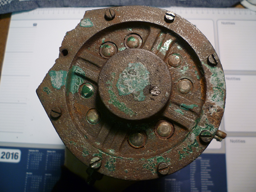

Step 3.
Loosen the front of the dynastart, also the 4 screws that are close to the axis. these screws are attached to a square plate behind the bearing. It is possible that these screws are very tight. You can then scare the screws by giving a few taps on the screws with a flat screwdriver and hammer, the screws will unscrew as it has.
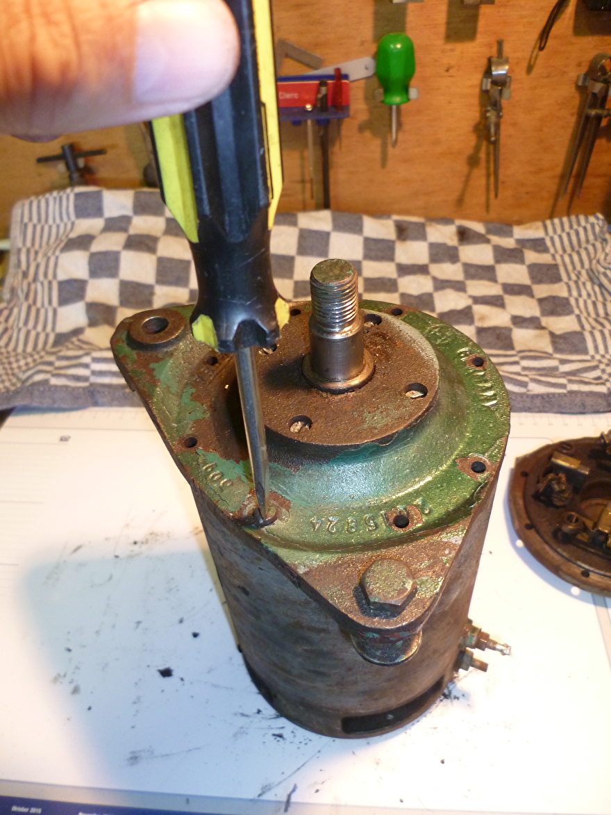

Step 4.
Remove the cover and pull the anchor out of the housing.

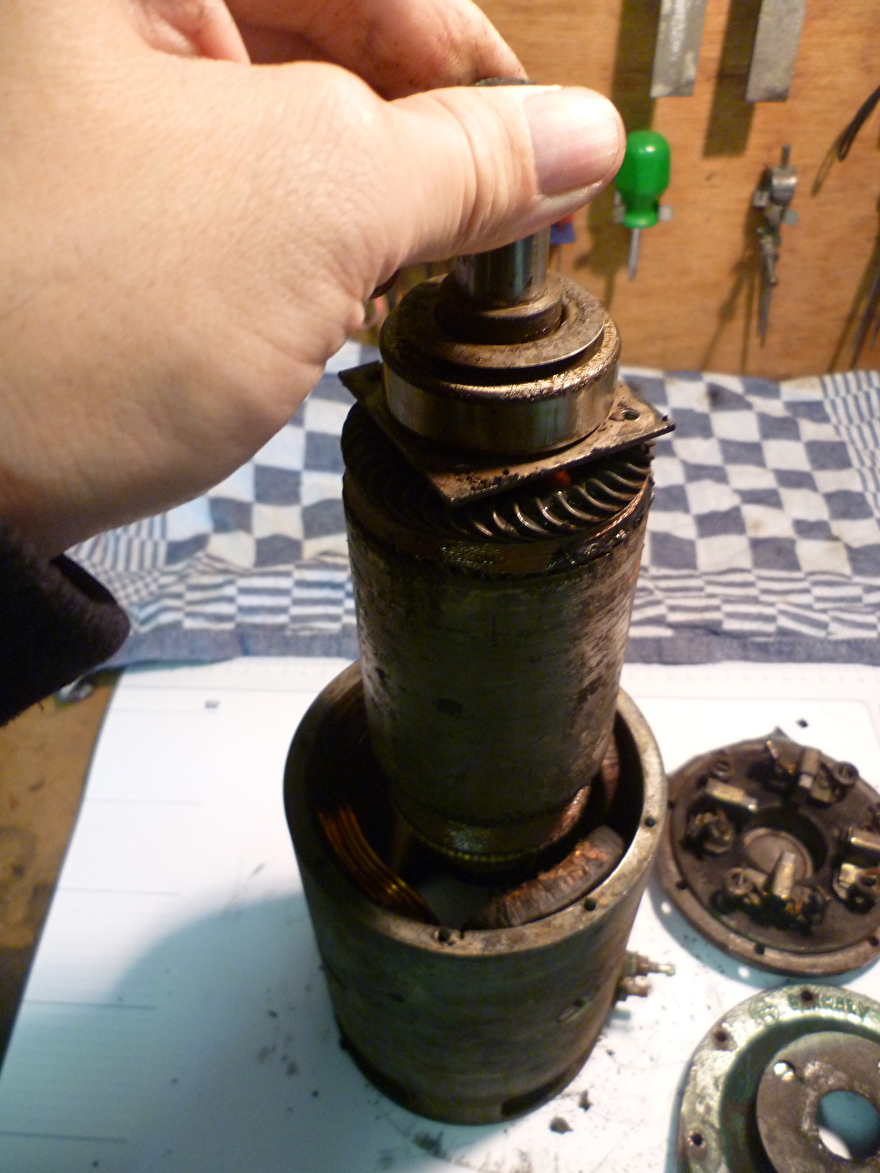

The dynastart parts side by side.
The field windings have become very dirty over the years due to dirt from the outside, but also due to the wear of the carbon brushes, the windings have become gritty. Cleaning the windings is not really possible, you often break more than it does well. You can remove dirt with a soft toothbrush, but be careful.
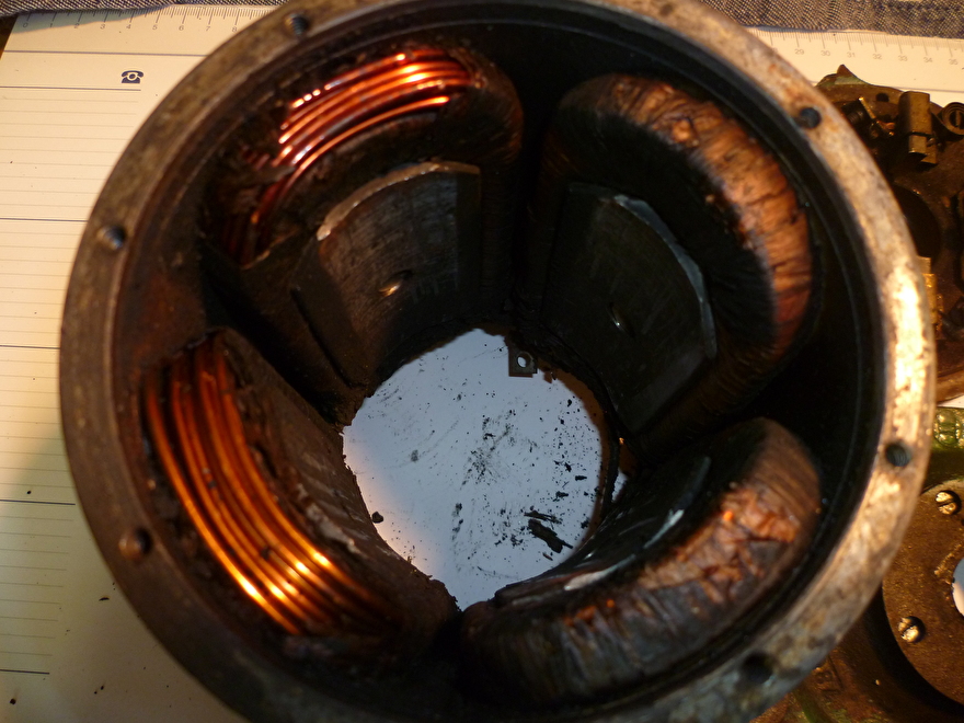
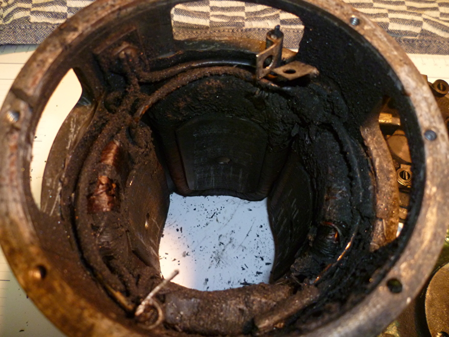
Step 5 Replace the carbon brush.
Photo 15 clearly shows that the carbon brushes have run out and there is one that is stuck in the carbon brush house. Carbon brushes are secured with a screw and the spring presses the carbon brush onto the anchor collector.

Koolbostel bridge.
Step 6.
Remove the carbon brush from the carbon brush holder by pushing it out, making sure that the spring remains.

Step 6.
Insert the new carbon brushes.

You can buy the carbon brush set in the web shop of this site.
Step 7 replace bearings.
If the dynastart is apart, it is wise to check the bearing if it is still good and replace it when in doubt.
The small rear bearing at this dynastart was worn out, this was determined by giving the bearing a blow and hearing if it creaks.
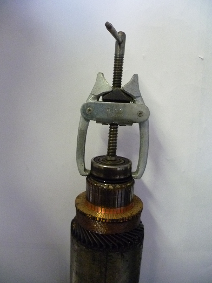
The rear bearing can be easily pulled off with a pulley puller.
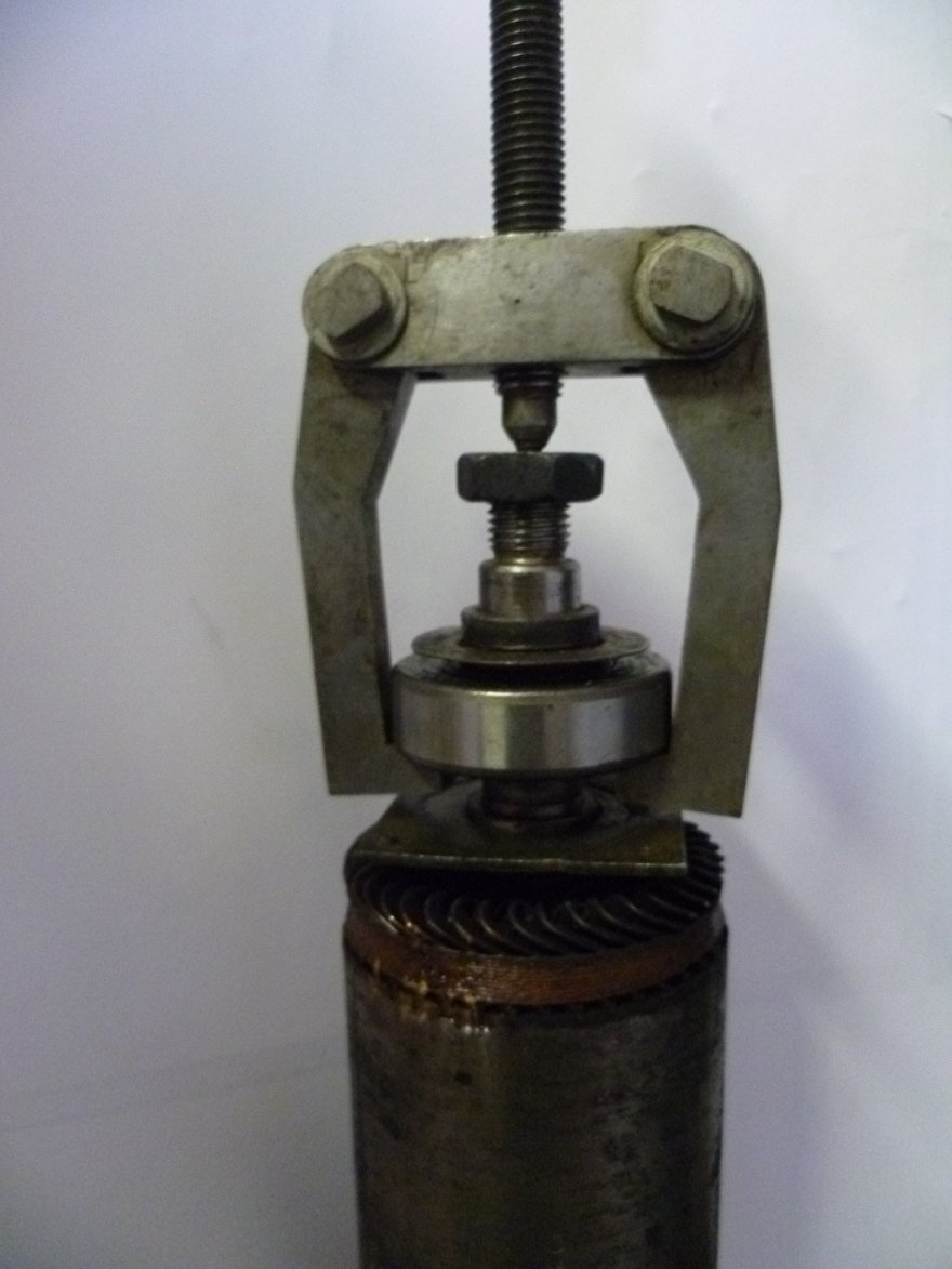
The front bearing has no room for a pulley puller. Some space must first be made to get the pulley puller under the bearing. I did this by laying 2 glue clamps under the square plate and resting it on a bench screw and the housing of the dynastart (see photo). Then tapped the shaft with a plastic hammer until there was enough space to get the pulley puller under the square / bearing plate.

Step 8 assemble the bearings.
Put the anchor in a vise with soft jaws and tap the large bearing on the shaft with a pipe. The pipe should have a larger diameter than the shaft but not larger than the inner ring of the bearing, this way you do not load the new bearing when you tap the bearing on the shaft in place. The ball bearing set can be purchased in the web shop.

Step 9.
Place the protective cap and spacer on the shaft of the pulley side.

Step 10.
Place the small bearing on the carbon brush side on the anchor. Pay attention!! in this case the bearing was flush with the shaft and you should tap the bearing on the shaft with a piece of flat rod so that the bearing is flush with the shaft. Before the bearing is pressed on the shaft, the protective cap must be replaced.

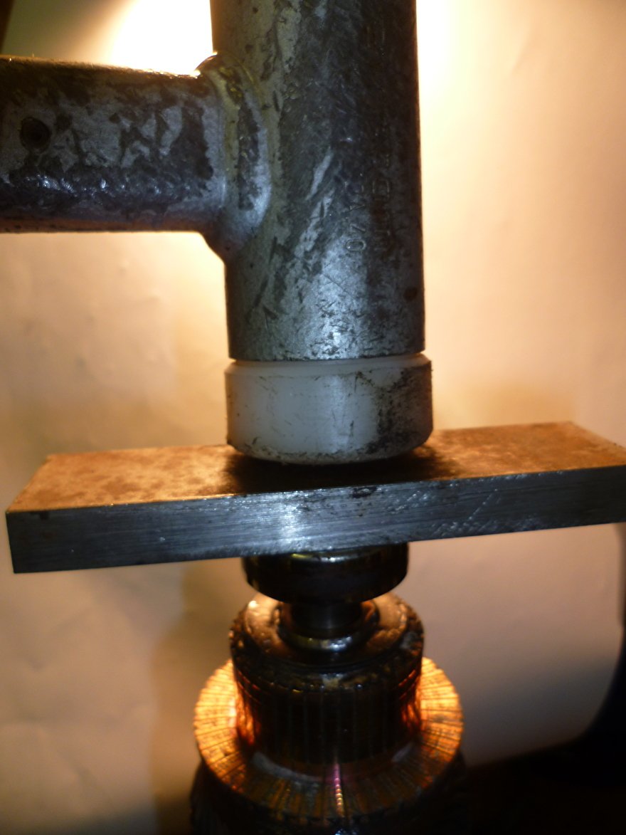

Step 11.
Now that the bearings and the carbon brushes have been replaced, the dynastart can be reassembled. Assembly is only possible in one way. Place the anchor with bearing in the back cover / carbon brush holder. The carbon brushes are in the way and must be pressed one by one with a small screwdriver to slide them over the collector.


The motor housing is then slid over the anchor.


The hole pattern of the rear lid is made in such a way that the lid can only be fixed in 1 way. This is done so that the attachment points of the dynstart that come back over and over with those of the motor and the carbon brush holder are reconnected properly.

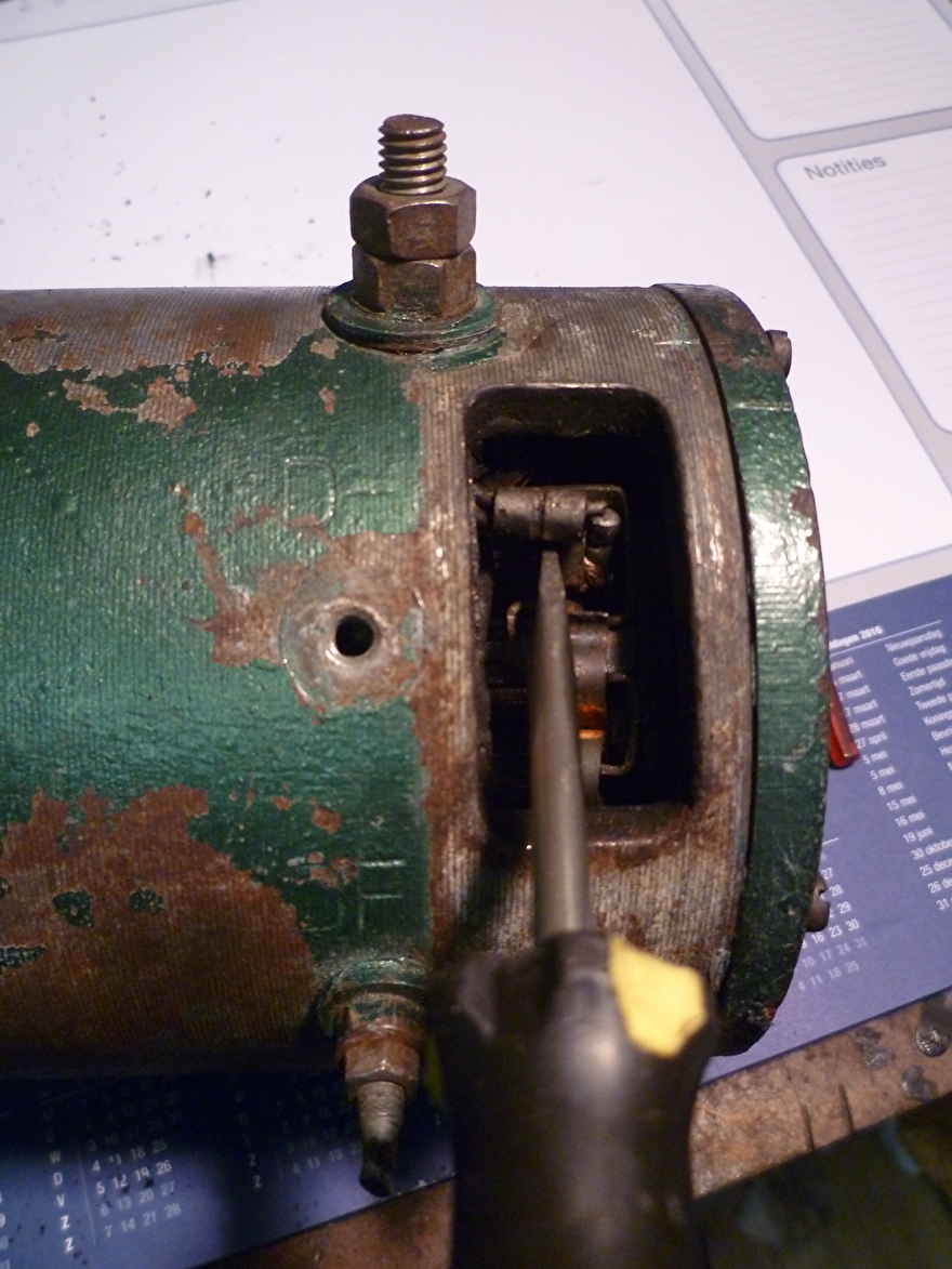
Step 12.
The front cover is put back in the same way as the rear cover, because of the hole pattern it fits in one way and the fasteners are in line. Tighten the outer bolts first and last the 4 inner bolts. When mounting the lid, it is useful to place the square bearing plate a bit on the eye so that the screws can be easily screwed in.

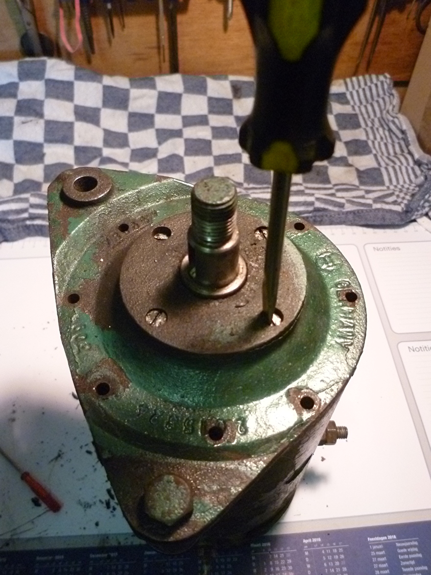
The dynastart is ready
We have a starting circuit with a starting relay 1, and there completely separated from a charging circuit with a voltage regulator that is operated by a relay with a common core.
In the dynestart there are 4 poles, 2 of which are wound opposite each other with thick wire, these 2 windings are in series and also via their own brushes in series with the armature to ground.
If we apply steam to this winding via the start relay, the series motor will therefore run.
The other 2 windings are wound with thinner wire are also in series but now with silk with its own brush parallel to the armature to ground.
The other side of this winding is the F (field).
The opposite brush on the armature is the D +. (61), which goes with the F to the controller.
The control lamp is connected to the ignition switch (15) the other side to the D + of the controller.
At rest, the controller D + is connected to F, so the light is connected to ground and fire via this field winding.
If the armature turns, then the current of the light through the field is sufficient to get the dynamo going, so there is voltage on D +, and with both sides plus on the light, it goes out!
If the voltage on D + is higher when the battery voltage is connected to the controller as B +, a relay in the controller will close and thus connect the D + to the B +.
A second line relay in the controller also powered from the D + controls the voltage at F and thus the output voltage of the dynestart.


